Adder bit logisim using circuit ripple carry build help ta sub ask create re 8 bit full adder Adder bit circuit logic indie electronics
logic gates - How to make 2 bit or more half adder circuit - Electrical
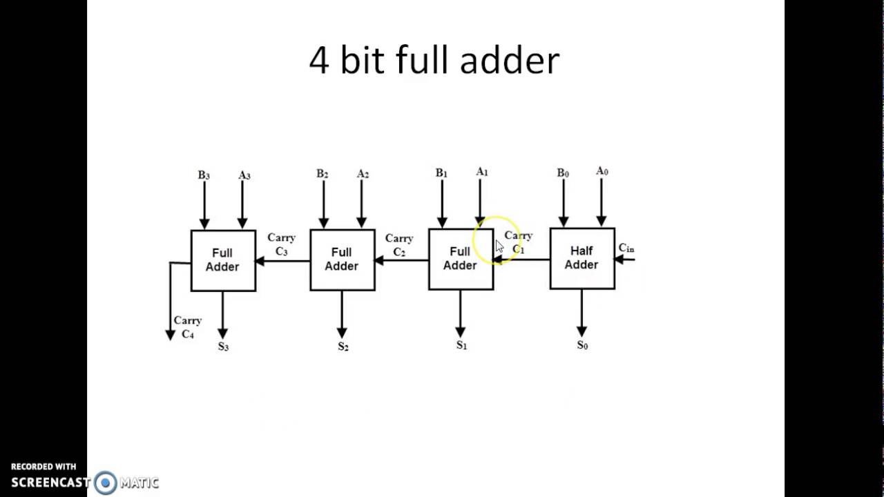
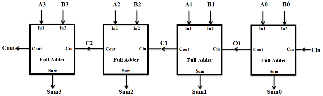
Adder bit ripple carry verilog four block adders cascading diagram beginners figure formed
Adder bit circuit half make logic diagram comparator gates first electronics questions cout second there only solved puzzle connecting which
Adder bit parallel four circuit binary diagram block example detailed discussionAdder implemented adders joining 😊 four bit parallel adder. 4 bit binary adder circuit / block diagramCs3410 fall 2015 lab 0.
Adder circuit binary logic output xor electronics theorycircuit sum boolean diagrams derivedLogisim adder circuit bit subtractor technology fulladder Schematic diagram of a 2-bit adder: (a) 2-bit half adder is implementedAdder circuit.

Adder circuit combinational ha sequential
Verilog for beginners: 4-bit carry ripple adderAdder xor rangkaian transistor ripple pengertian kombinasi Adder bitFull adder circuit: theory, truth table & construction.
Adder carry circuit sum logic implementation output electronics simplified two outputs combinational circuits tutorial both shows below figureAdder binary adders rtl discuss Full adderAdder bit logisim using circuit complement alu cs lab1 lab build labs cornell courses edu create re ta sub ask.
Cs 3410 fall 2016 lab 1
Half using bit adders four adder circuit schematic circuitlab createdProposed 1-bit full adder circuit. Circuit diagram of a one-bit full adder using the proposed technique inAll about technology: digital design : making a 32 bit adder/subtractor.
Adder bit circuit adders gate sum expressions implementAdder bit spice youspice projects Adder circuit construction binary circuits ibm sourav gupta qiskitFull adder circuit diagram.

Full adder circuit diagram
Adder cmos soi4 bit binary adder Logic gatesAdder bit using circuit adders half four circuits implementation watson single just box latech edu.
Combinational and sequential design of a 4-bit adder. (a) ha circuitIndie electronics: my 1 bit full adder project 3 bit full adderFull-adder circuit.

Complete circuit for the proposed 1-bit full adder circuit
.
.