Circuit design 4 bit parallel adder subtractor with bcd 7 segment Adder bit subtractor circuit diagram block using logic draw Subtractor half vhdl circuits circuit designing table truth sub tutorial
Circuit design 4 bit Parallel Adder Subtractor with BCD 7 Segment
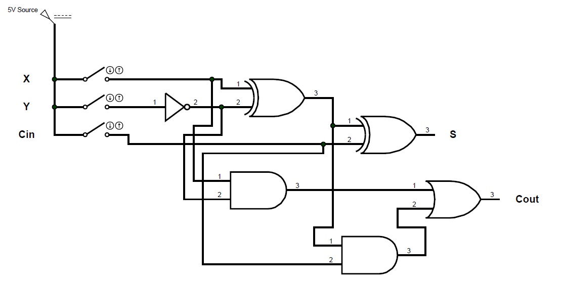
Ece logic circuit: full subtractor
Full subtractor logic diagram and truth / 4 bit binary adder subtractor
Subtractor logic circuits combinational implementationAdder bit subtractor binary circuit circuitlab description Tinkercad adder subtractor bcd circuitBinary adder/subtractor.
Subtractor adder realization quantumSolved consider the 4-bit adder/subtractor circuit displayed 4-bit 2’s complement format adder/subtractor circuit(solved) : prototype shown implements 2 bit subtractor using cascaded.
![(Solved) : Prototype Shown Implements 2 Bit Subtractor Using Cascaded](https://i2.wp.com/d37djvu3ytnwxt.cloudfront.net/assets/courseware/v1/1a01f8d074d3201a5327b6f150be8a2d/asset-v1:MITx+6.004.1x_3+3T2016+type@asset+block/sequential_sequential.SP13_Q1_P5E.png)
Subtractor bit implementation comparator using mux 2bit helps hope information these stack same
Subtractor cascaded implements prototype combinational register timingAdder bit subtractor circuit values following consider input mode has help steps solve thank solved questions Full subtractor circuit and its constructionFigure 2 from a novel approach for reversible realization of 8-bit.
Complement circuit bit multisim adder subtractor 2s2-bit binary adder/subtractor Full subtractorSubtractor circuitdigest.
![Circuit design 4 bit Parallel Adder Subtractor with BCD 7 Segment](https://i2.wp.com/csg.tinkercad.com/things/7cAgQSLqhDZ/t725.png?rev=1604236024414000000&s=&v=1&type=circuits)
Vhdl tutorial – 11: designing half and full-subtractor circuits
Subtractor circuit logic table truth diagram schematic ece obtain nowAdder subtractor logic add sub combinational circuits bit binary using subtraction tutorial adders electronics Subtractor logic truth combinational inputs outputs adder subtracting proteus geeksforgeeksSubtractor circuit half circuits.
.
![Full Subtractor Logic Diagram And Truth / 4 Bit Binary Adder Subtractor](https://i2.wp.com/www.theengineeringprojects.com/wp-content/uploads/2021/02/full-subtractor-3.png)
![Subtractor Circuit – Half Subtractor, Full Subtractor, How it Works](https://i2.wp.com/electricalfundablog.com/wp-content/uploads/2020/07/Introduction-to-Subtractor-Circuits.jpg?fit=649%2C380&ssl=1)
![Binary Adder/Subtractor | Combinational logic circuits | Electronics](https://i2.wp.com/www.electronics-tutorial.net/wp-content/uploads/2015/05/Add_Sub.png)
![Full Subtractor | Combinational logic circuits || Electronics Tutorial](https://i2.wp.com/www.electronics-tutorial.net/wp-content/uploads/2015/09/full_sub-1024x650.png)
![Full Subtractor Circuit and Its Construction](https://i2.wp.com/circuitdigest.com/sites/default/files/projectimage_tut/Full-Subtractor.png)
![ECE Logic Circuit: FULL SUBTRACTOR](https://2.bp.blogspot.com/-00aQW1bsy0A/T1SxT9p2Z3I/AAAAAAAAAFo/WagwWGAm99E/s1600/schematic+diagram.jpg)
![Figure 2 from A novel approach for reversible realization of 8-bit](https://i2.wp.com/d3i71xaburhd42.cloudfront.net/147db51cf0f054b260d980950c01146649483aa1/3-Figure1-1.png)
![Draw the logic diagram of a full adder. Create a 2-bit adder-subtractor](https://i2.wp.com/cssimplified.com/wp-content/uploads/2015/01/Adder_Subtr_2_bit.jpg)