Circuit flip gates logic flops made counter Binary counter circuit diagram Calculator routing node
digital logic - Issues with 4-bit counter when porting to PCB
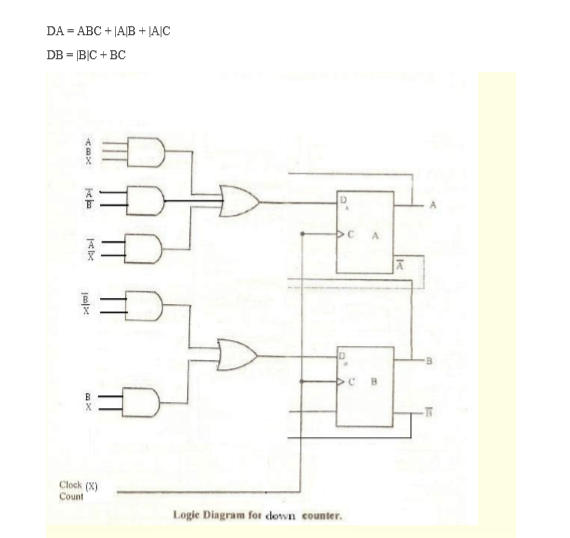
Counter bit down circuit diagram digital
Solved a two-bit counter has the following circuit diagram.
Counter binary bit electronics projects tutorial mini iv circuit4 bit binary counter Digital logicGadgetronicx circuits.
Counter bit schematic using porting pcb issues when logic simulate circuitlab created stackCircuits binary 4 bit down counterDigital logic.
Digital logic
Circuit designing & firmware development: counters tutorialSolved a two-bit counter has the following circuit diagram. Counter bit ripple binary trigger clock question edge transcriptions count willCounter bit circuit two has solved diagram following transcribed problem text been show state.
Counter circuitsBit counter schematics The 3-bit counter circuit.Counter bit parallel binary using logic.
![4-Bit Binary Counter with Parallel Load. | Download Scientific Diagram](https://i2.wp.com/www.researchgate.net/profile/Mohammad-Samadi-Gharajeh/publication/239337459/figure/download/fig11/AS:298955373072390@1448287923277/4-Bit-Binary-Counter-with-Parallel-Load.png)
4-bit binary counter with parallel load.
Binary theorycircuitBit circuit counter two has diagram solved following output transcribed problem text been show draw Counter bit schematic repeat clocks each after digital circuit engineering logic circuitlab created using stack[solved] question 04: design a 4 bit binary ripple counter that trigger.
Design a two bit counter circuit that counts from 0 to 2 only, that is .
![Circuit Designing & Firmware Development: Counters Tutorial](https://3.bp.blogspot.com/-zEyR8aW3ewo/UF_r8SAwY5I/AAAAAAAAA_U/Uk0dDYpDDn8/s1600/3.gif)
![Solved A two-bit counter has the following circuit diagram. | Chegg.com](https://i2.wp.com/d2vlcm61l7u1fs.cloudfront.net/media/52e/52e88aa7-51af-4d49-82e6-ecacf34ca7cf/phpWwfWqG.png)
![Solved A two-bit counter has the following circuit diagram. | Chegg.com](https://i2.wp.com/d2vlcm61l7u1fs.cloudfront.net/media/ad3/ad34d5a6-9064-47fd-b162-a76fc300d2d3/phpbPJxRS.png)
![digital logic - Issues with 4-bit counter when porting to PCB](https://i2.wp.com/i.stack.imgur.com/4cleX.png)
![binary counter circuit diagram - theoryCIRCUIT - Do It Yourself](https://i2.wp.com/theorycircuit.com/wp-content/uploads/2018/08/binary-counter-circuit-diagram-1024x436.png)
![Digital Logic](https://i2.wp.com/www.fwdskillzone.com/uploads/4/6/8/4/46843999/binarycounter_orig.png)
![digital logic - 3 - bit Counter (repeat after each 6 clocks](https://i2.wp.com/i.stack.imgur.com/Sxvt8.png)
![4 bit binary counter - Circuits - Circuit Diagram](https://i2.wp.com/api.circuit-diagram.org/document/store/render/2398800b797c4e6aa0f95f1e575c02fb.png?h=6de515)
![Design a two bit counter circuit that counts from 0 to 2 only, that is](https://4.bp.blogspot.com/-9KT7WpXyPV4/WtWOa06k-9I/AAAAAAAAIfk/wp9CTVVu108Wi4Y3X7cNv37u9RvzAaLfwCLcBGAs/s1600/Screenshot%2B%252876%2529.png)
![6 bit counter schematics. | Download Scientific Diagram](https://i2.wp.com/www.researchgate.net/profile/Senentxu_Lanceros-Mendez/publication/224311777/figure/download/fig1/AS:393728339529728@1470883559664/6-bit-counter-schematics.png)