Ir sensor switch with ic 4017 project Integrated circuit Simple touch switch circuit using transistor, 4017, 555 ic
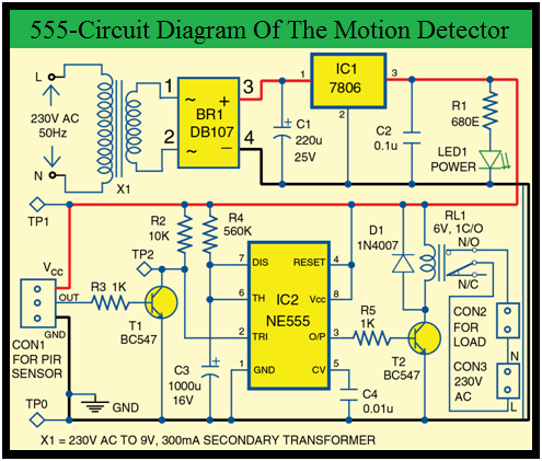
WattruBlog: NE555 Timer base PIR Motion Sensor
Wattrublog: ne555 timer base pir motion sensor
Pir motion circuit timer sensor sensors diagram
Flip-flop timer using 4017Ne555 photoresistor using schematic circuit circuitlab created stack 4017 led chaser circuit diagram with rgb ledHow to understand ic 4017 pinouts.
Cmos timer sequential build use circuit click diagram prototype photograph gr nextLight dancing circuit diagram 4017 circuits projects electronics electronic led digital function lights ic using leds pcb schematics board integrated 4017 circuit dice diagram example datasheet4017 circuit circuits cd scanner 1d simple gif chip talkingelectronics explain please projects integrated data leds electronics kitt.

Build this diy stopwatch using digital ic 4026 and 4017
Circuit 4017 cmos sequential diagram timer using circuits build schematic seekic timers control gr next sequence ic above click sizeHow to use a cmos 4017 to build a sequential timer Circuit timer flop flip 4017 using circuits diagram reset schematic current clock flipflop gif gr nextSensor pcb easyelectronicsproject.
Motion sensor light switch using cd4017 & ir sensor with circuitPcb cd4017 4017 switch using proximity off cd automatic circuit circuits diagram led related ldrHow to use a cmos 4017 as a toggle switch under repository-circuits.

Circuit switching using
Sensor circuit schematic diagram for switchExplain this simple 4017 circuit please... 3 simple proximity sensor circuitsUnderstanding ic 4013 pin-outs and specifications.
Piezo transistorSwitching using circuit arduino leaning towards handle am 4017 circuit cd4017 receiver easyelectronicsprojectCircuit switch toggle diagram relay 4017 cmos wiring control timer push button cd4017 digital fan use schematic circuits reset power.

Circuit proximity detector diagram infrared motion alarm simple sensor circuits lm567 using build ir security ic homemade object theft obstacle
Ic datasheet circuitsIr sensor switch with ic 4017 project Stopwatch digital diy 4026 ic 4017 circuit using block diagram build segment gadgetronicx displayLed chaser using 4017 counter and 555 timer.
4017 led chaser 555 pcb using timer counter bottom ic4017 ic project circuit diagram Cmos 4017 sequential timer circuit diagram and instructions4017 chaser rgb easyelectronicsproject.

Remote control switch circuit using 4017
.
.